Right handed Silvertone
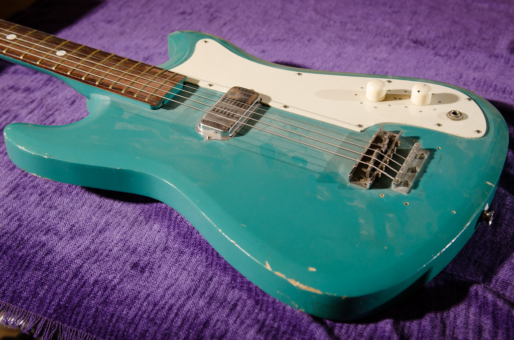
Here is a project to help out you left handed players out there. A customer wanted to have his old Silvertone converted into a left handed guitar. You can see how the controls and instrument cable would be right in line with the player's picking hand when playing it left handed. Although the guitar is played left handed, it is not strung like a left handed guitar. Pictured below, for example, is the Philadelphia guitarist Kenn Mogel of the band Pyschedelphia (former). He is an absolute beast and plays left handed with the guitar strung like a right-hander. This is unlike Jimmy Hendrix's guitars that were strung lefty. I asked him how fingerstyle works for him and he says "great, I have four thumbs!"

Kenn Mogel (of the former Psychedelphia) and his left-handed Artinger guitar. Strung righty, played lefty. Note the bass strings are towards the floor. Photo © Kevin Chubbuck

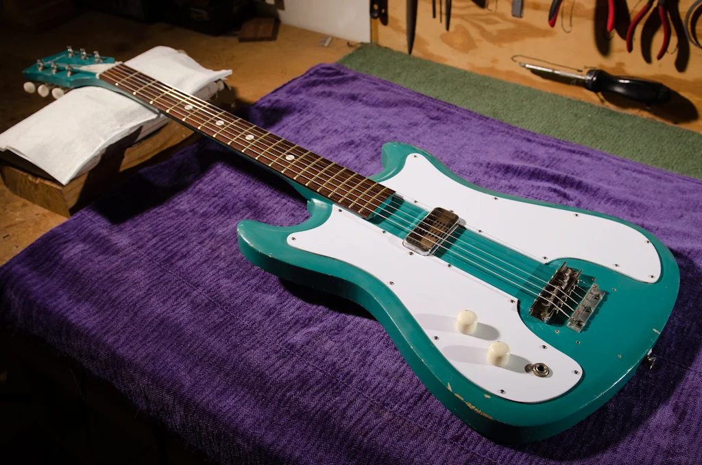
“Stock” Silvertone
So in order to make this more comfortable to play left handed, we need to move the controls to the other side.
This will involve making two pickguards:
- One "dummy" guard that will be identical to the original (without control mounting holes) to cover the original control cavity.
- Another "lefty" guard for the new control location.
The body will need to be routed for a new control cavity on the other side of the body as well.
So the itinerary:
1. Original pickguard needs to be removed along with the electrical components.
2. A new "dummy" guard made identical to the original minus the control mounting holes.
3. Finally a new "lefty" guard needs to be made along with the new control cavity.
: : : : : :
Let the photo essay commence!

Let’s move these controls to the other side to get them away from the player’s picking left hand.

Pickguard assembly is removed.

The bare-bones circuit: single pickup, volume, tone and output jack.

Pickup riveted to pickguard, needs to be drilled out in order to remove.

Proposed left handed pickguard. Note that the output jack will have to be rewired.
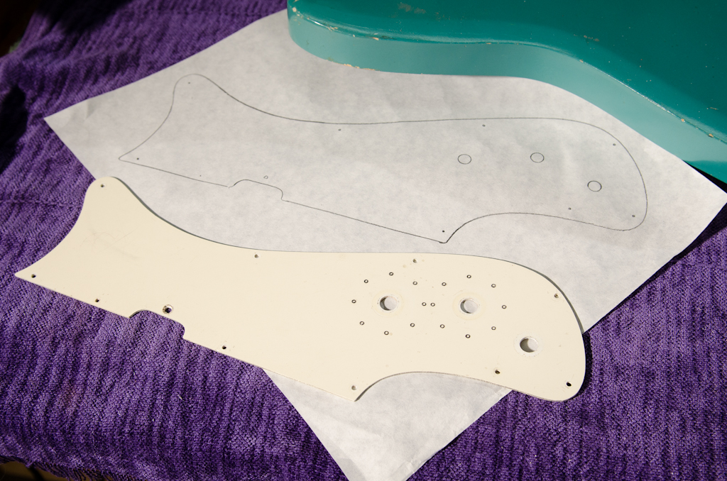
A good practice is to make a copy before using the original pickguard as a routing template should things go south on the router table. This “dummy” guard will replace the original, minus the control holes.
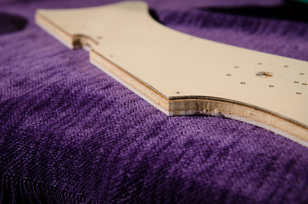
First we need to make a “dummy” guard without any control holes to cover the original control cavity. Here is my router sandwich. There is a gap between the bearing and the blades of my router bit, so I need to space the new pickgaurd away from the original “template”. Top is the original, middle is scrap plywood, bottom is the new “dummy” guard.
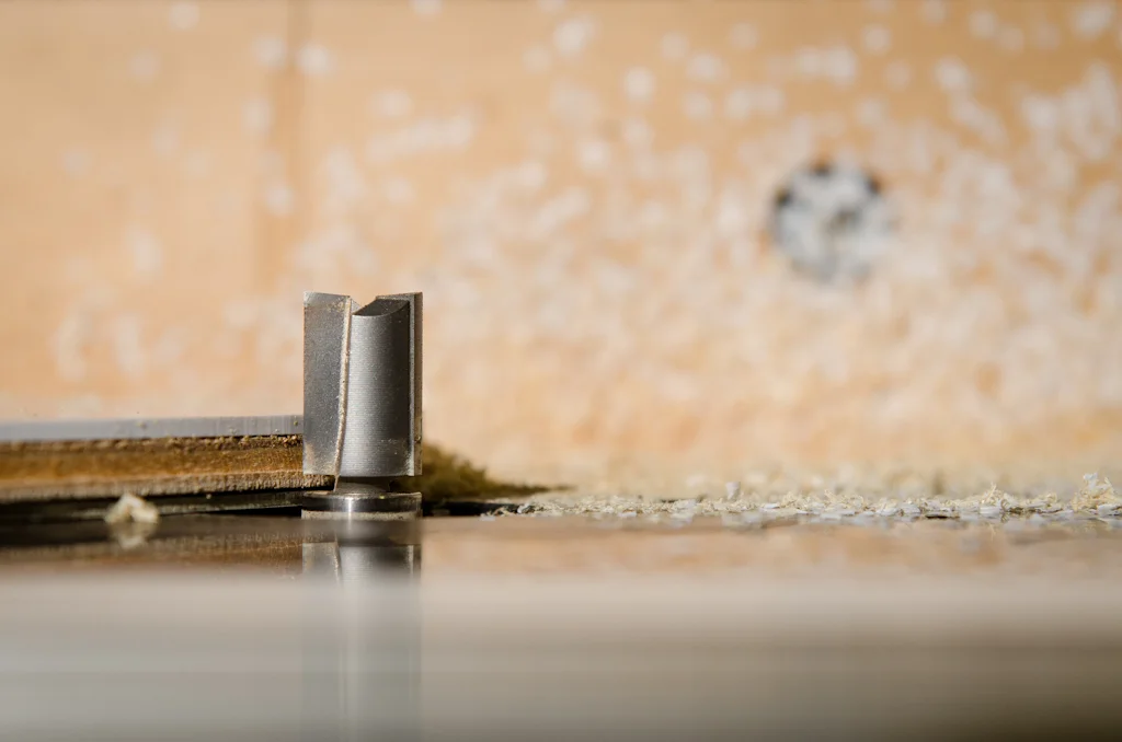
A close up of my router bit. Note the gap between the bearing and the blades of the bit. The original pickguard is on the bottom and rides against the bearing.
Here is the sandwich after routing with the router gap left in the scrap plywood. This “dummy” guard is now shaped and identical to the original, minus the control holes.

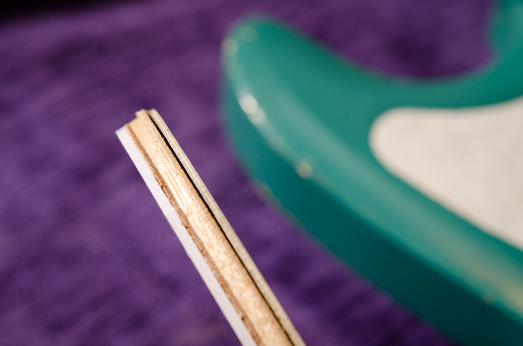
The original pickguard sat on top of the pickup mounting flange and did not allow the pickguard to sit flat against the body. Here is the layout of the material to remove in the guard to allow it to accommodate the flange.

The new pickguard is routed to allow the pickup to sit on the body and the pickguard(s) to lay flush on the body too. I did this relief cut on both new guards.

Now for the other side: the new control guard. The body is asymmetric, so the new “lefty” guard has to be cut and shaped by hand. I used the pickup side of the original guard to layout the inside of the new lefty guard.
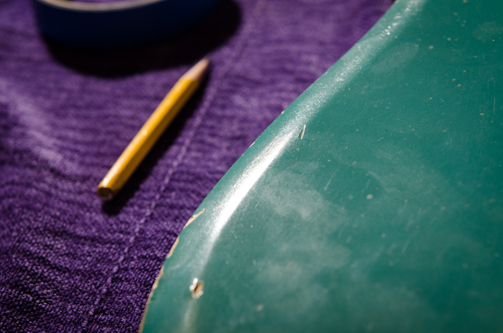
I use the bevel as my reference point to trace the outside of the lefty guard on the previous photo.

After the template is trimmed to the bevel mark, I use a compass to space the line further inwards.

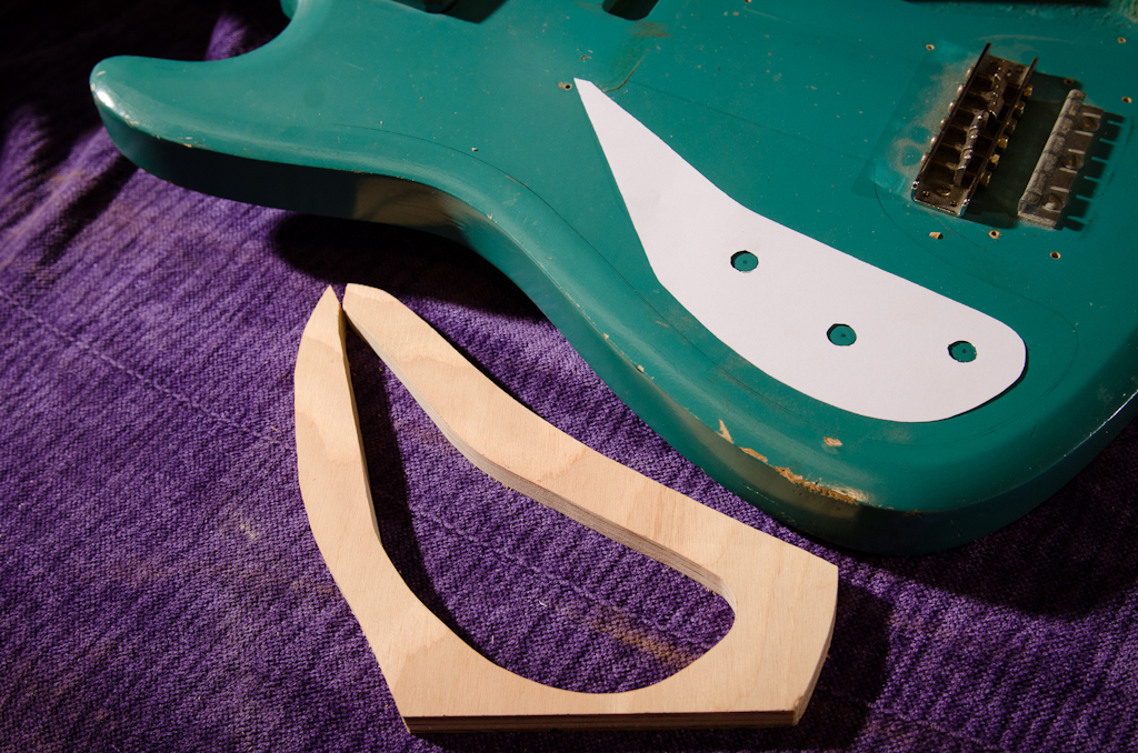
The finished lefty template, ready to transfer to the pickguard stock and cut and shaped.

The pickup was originally riveted to the pickguard on the control side, so I glued a dowel into the control cavity to fasten the pickup to.

Another view of the added pickup mounting dowel.

Yet another view of the pickup mounting dowel to secure the pickup.

Both new pickguards are finished: 1. the replacement guard without the control mounting holes, and 2. the new lefty guard for the new control location.

The new lefty guard – the output jack needs to be rewired to fit the new lefty “mirrored” layout.

The output jack is rewired. Note that I traced around the controls to layout the new control cavity that will have to be routed into the body.

The control cavity tracing is photocopied so I can make a routing template. Note that above on the body I transferred the new control hole locations.

The photocopy is cut out and used to layout both the cavity location on the body, and the routing template made of scrap plywood. I use the control mounting holes in the new lefty guard to “center” the routing template location using my control hole marks on the body.
Here is my quick and dirty routing template that will be held in place with double-sided “carpet” tape on the body.

The routing template is “stuck” to the body with the double-sided tape. I use the paper template to locate the position of the plywood routing template.

A router bit in combination with a collar to begins the new control cavity.
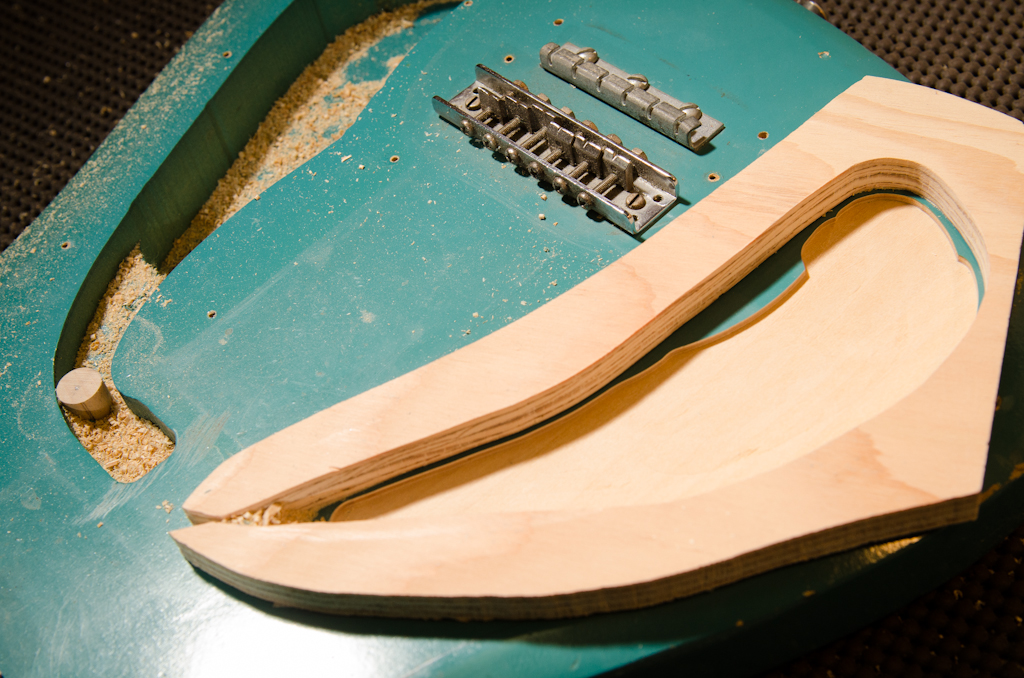
Originally I thought I was going to use a thicker piece of plywood for this template. This plywood was too short to allow the router base clear the bridge, so I had to remove the hardware. No biggie.

Here is the cavity so far, with some freehand routing to transition down into the deeper main cavity. This maxes out my collar-cutting setup as my bit is not long enough to go to full depth.
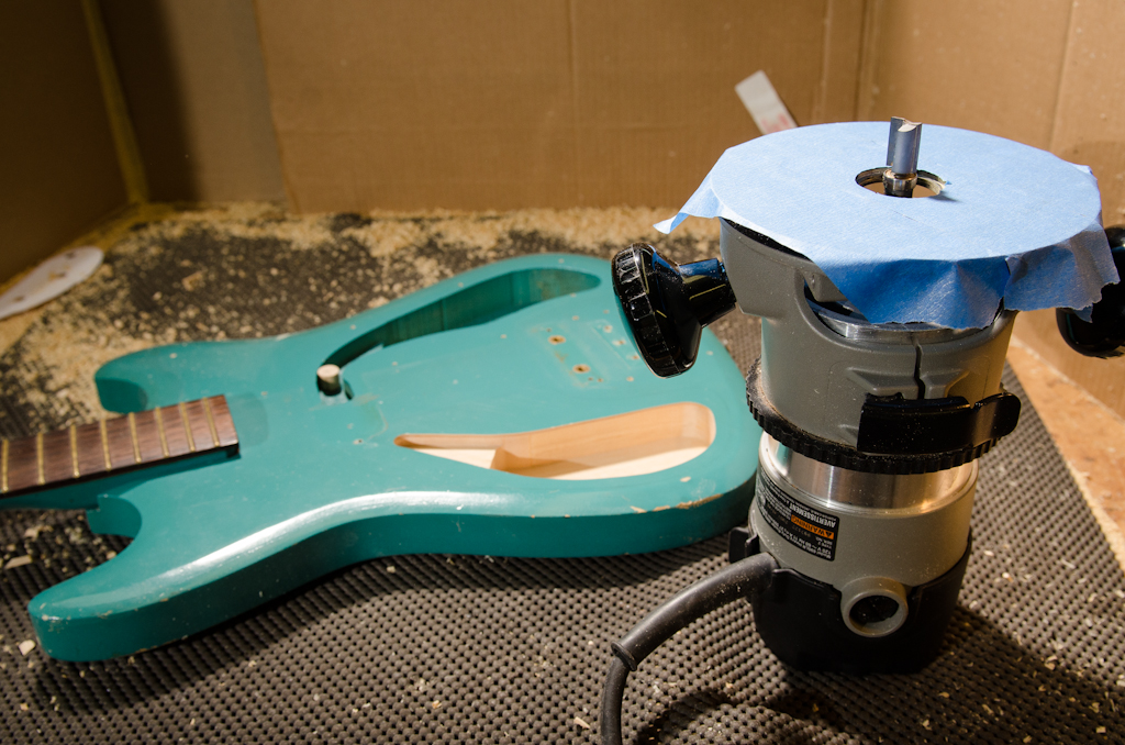
I switch to a bearing router bit to finish off the cavity. The template is removed and the bearing will flush-trim off of the established cavity walls. I tape the base of the router to help protect the guitar’s finish.

Here is the finished cavity. Note that I used a smaller router (freehand) to finish up the tip of the cavity to accommodate the pickup’s lead wire.
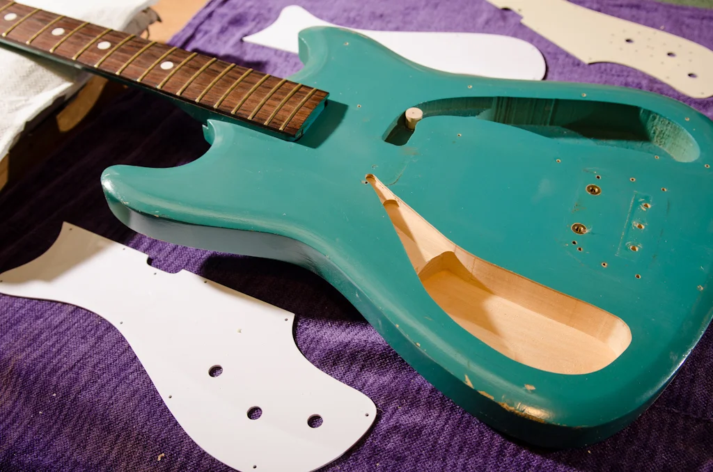
The new lefty guard and control cavity.

The finished lefty conversion with dual guards. Note that the strings are still strung like a right-handed guitar.

Left handed Silvertone. No more instrument cable and control knobs digging into the player’s forearm.
The customer is really happy with his new guitar. I can sympathize with left handed players. It is a right handed world and options are extremely limited for those on the right-handed outcasts. Can you righties imagine playing left handed? It feels so damn awkward, right? I have a 2-year old daughter that I am casually teaching to play guitar. Anytime she grabs the pick with her left hand, I cringe! To each there own, but I hope to keep that pick in her right hand !) !!!